Extracting Non-Planar Views from Curved Planes
Dragonfly also includes the option to unroll tortuous planes using free form surface inspection tools, such as Bezier patches (shown below) and Visual RBF rectangles. With these tools, you can adjust the control points in non-planar and 3D views, add control points, and extract data as a one-slice image for inspection and reporting.
Bezier patch

-
Draw a rectangular region on the view with the Rectangle tool that best corresponds to surface you want to inspect, as shown below (see Using the Region Tools).

- Right-click the annotation in the Data Properties and Settings panel and then choose Create a Bezier Surface or Create a Radial Basis Function Surface in the pop-up menu.
-
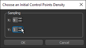
Choose an initial control points density in the dialog to appears, as shown below.
-
Click OK in the Choose an Initial Control Points Density dialog.
A Bezier patch or Visual RBF rectangle is added to the Data Properties and Settings panel.
- Select the view in the workspace in which you want to unroll the plane.
-
With the patch or rectangle selected in Data Properties and Settings panel, choose Non‐planar 2D view in the View mode drop-down menu on the Scene’s Views Properties panel, as shown below.
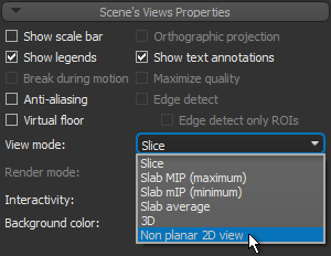
The non-planar view extracted from the surface of the curved plane appears.
-
In a 2D non-planar or 3D view, adjust the patch or rectangle with the control points so that it corresponds to the surface that you want to inspect.
You will need to hold down Left Ctrl to move a control point with your mouse. This is the default for the configured action for 'Move the surface control points' (see Configured Actions for Non-Planar Views).
Note You can redistribute and sample the control points while you work by right-clicking the patch or rectangle in the Data Properties and Settings panel and then choosing Redistribute Control Points in the pop-up menu.
Note You can also edit the shape property 'Thickness' in the Shape properties box. This setting determines the weight of the lines and control points.
-
Extract a projection of the non-planar view, if required (see Extracting Projections from Non‐Planar Views).
